Showing posts with label stator. Show all posts

Tuesday, May 22, 2012

Summer Project Progress

With my first year at BU finished, I am now free to start as many projects as I think I can complete in the next four months. I have two new projects completely established and started, two tentative ventures having to do with watercraft, and of course that pesky hub motor scooter I've been 'working on' for the past ...10 months or so.

One of the established projects will remain off this blog until a certain friend has a birthday. The other project is a gas-to-electric conversion of a minibike which was kindly donated to me by Charles.

Stripped of all the fancy stuff.
The stator is Delta-wound, which means that if you uncoiled all the teeth and didn't remove any of the electrical connections, you'd have a triangle. My first hub motor is wound in a Wye configuration where all three phases meet in the middle. Delta-wound stators tend to spin faster while producing less torque per amp. If you had two stators of identical dimensions, number of wraps, voltage, etc., but one was wound Delta and the other was wound Wye, the Delta would produce less torque and higher rpm by a factor of √3.

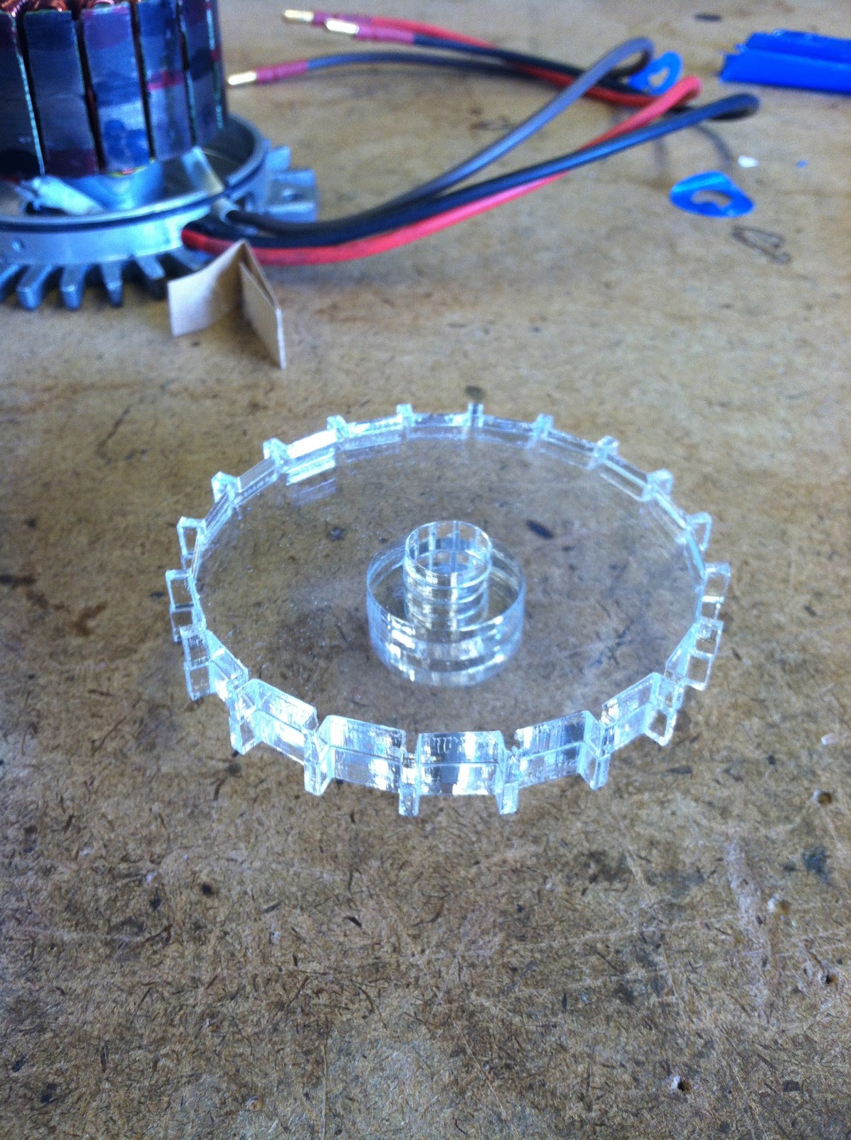
Standard procedure for brushless motors is to open them up to look for stray windings, bad connections, or misaligned magnets. Boy, did I find some misaligned magnets. A quarter of the forty magnets in the can had come off and had clumped together in a few locations. A jig for positioning the magnets was lasercut from .25" acrylic. I wanted it to be clear so I could see both ends of the magnets. The acrylic worked very well, and after the epoxy between the magnets and the can had set for about two hours, I added some epoxy between the magnets to prevent slippage side to side.


N = 51... ?
Magnet meeting
Magnets removed, old epoxy removed, can surface sanded to better accept new epoxy.
Jig for positioning magnets.
Epoxy added to the gaps between magnets to help prevent them from sliding. Looks good! 

After the magnet epoxy was allowed to cure for 24 hours, I brought it to the Edgerton Center shop to try to use a lathe to gently lower the can onto the stator. Credit for this idea goes to Ed Moriarty, and the hands you see in the pictures are those of Mark Belanger, who helped me figure out how to do this and offered to do the procedure due to my damaged left wrist. Mark came up with the idea of turning the end of a shaft to a point that would fit into the tapped hole at the front of the shaft connected to the can. The shaft was held in the chuck on the right, and the can was firmly held in the chuck on the left. The stator assembly was placed over the shaft and was advanced so the two shafts met and could not move. The stator was carefully moved towards the can and was 'sucked' into position while maintaing the proper alignment thanks to the lathe setup. The motor was then fully pushed into its bearings with the tailstock.

Note: lathe was not spinning during these photos. 


It looks the same as it did before, but here's that picture again.


Monday, January 9, 2012

Stator Wrapping Complete!

It's a milestone in an engineer's life when he completes the wrapping of his first stator for a custom brushless D motor. I'm proud to announce that I have hit that milestone, and my thumbs are killing me. First step was to make a diagram for wrapping, which can be found in this post. Over the course of the next 10 hours (not consecutive), thumb and finger health decreased steadily and a few pictures were taken. To help you understand the numbers in the captions, one "Phase" consists of two pairs of two strands (four strands total) each wrapped around two teeth (four teeth total). The A phase consists of two teeth wound clockwise and two teeth wound counterclockwise. Put three of these phases together in the right order with the right orientation, and you've got yourself a motor.

1/4 of phase A wrapped
1/2 of phase A and 1/2 of B wrapped
Phases A and B complete, 1/2 of Phase C
One more tooth to go!
DONE. GORGEOUS.

Finishing this felt amazing (as I loudly proclaimed in N52 when I completed the last turn) despite my throbbing fingers. I've technically been working on this project since late August, and I'm finally getting somewhere. Shortly after I posted this photo to facebook, Shane and Charles displayed their amazement with the quality of the wraps, which is apparently pretty good. Which was what I was aiming for. The next step will be machining the endcaps and spacers to house the stator and rotor. Too bad I'm going back to school in a week and I'm helping the MIT Marine Robotics Team with some stuff until then.

Looks like it's time to get reacquainted with the machine shop. Let the hub motor season begin.

Thursday, January 5, 2012

Stator Wrapping and Xbox Case Mod Preview

I finally got off the ground with (name TBA) scooter's drive system. After many months of planning and procrastination, I began wrapping my stator... and boy do my thumbs hurt. Shane told me before I began that there is a spectrum of quality of stator wrapping from neat and meticulous to quick and dirty. I chose to pursue the neat and meticulous path because a more tightly wound stator would be a more powerful one. A side effect of this path is that my right thumb and forefinger are now throbbing from pulling as hard as I could on wire for an hour straight. I am not looking forward to wrapping another 11 teeth, but it must be done!

This just popped into my head: I might call this project Time Scooter. Because I've been working on it since August. We'll see if the name sticks.

Here are some pictures from the day:

Wrapping configuration diagram
Wrapping two strands at the same time is tough.

Another project I've been doing on the side this past week is creating a clear case for my xbox made from acrylic. Unfortunately 3-402 has been (hopefully temporarily) closed before MIT's IAP starts, at which point it will be occupied full time by a class. I haven't been able to make any new parts, but I have started to model the case in SolidWorks. So far I have taken my Xbox apart four times, designed and made a prototype of the motherboard mount... and that's about it. I was aiming to complete this project before school starts again, but that might not happen because of the fabrication delay.

Let's see what this thing looks like on the inside.


What an Xbox looks like on the inside.
Might be tough to see (it's clear!) but here we have the first version of the motherboard mounting piece.

Hard drive module, disassembled
Ideally I will buy a ~120 Gb 2.5" hard drive and format it to xbox's native system so I don't have to spend exorbitant amounts of money for a tiny amount of space. The current drive was $80 for a 20 Gb USED, which I find to be absolutely ridiculous.

ALASKA UPDATE!
I just got off the phone with Ed Moriarty, who is currently in McGrath, Alaska, and he says the Aurora Bears are a huge success! The kids up there are having a great time making the bear assemblies, and even the superintendent of schools showed up to make one!

Sunday, November 13, 2011

New Scooter

Here's to actually doing projects and having fun doing them. The long anticipated construction of New Scooter (official name TBA, not to be confused with Pneu Scooter) finally got its butt off the couch and went to the whiteboard for some calculations.

So lets say that I want to be able to climb a 10% grade on my scooter.

F = mg sin(theta)
F = 75 kg * 9.8 m/s^2 * .1
F = 73 N

This means that the force of gravity pulling me back down the hill is 73 N, and that I want 73 N pushing me up the hill. Lets say I want to climb the hill at 5 m/s.

P = linear force * linear velocity
P = 73 N * 5 m/s
P = 365 W

Torque = Force * radius, and I have a 6" diameter wheel.


T = F * r
T = 73 N * .076 m
T = 5.55 Nm

I'm planning on building a 33 volt LiFePO4 battery.


365 W = 33 v * 11.1 A

Now for my new favorite equation: Tea is for nibbler. I mean T = 4NIBLR

That is, Torque = 4 * # of wraps * Current * Strength of magnetic field * Length of stator * Radius of stator

For this calculation, we will estimate that the B field is about 1 T. This is an estimation, but it's really not far off of the actual value.

T = 4NIBLR
N = T/4IBLR
N = 5.55 Nm / 4 * 11.1 A * 1 T * .0254 m * .034 m
N = 144 wraps per phase

Now lets say the maximum current through quadruple 22 guage (four strands in parallel) wire is 40 amps peak. Replacing the 11.1 A in the equation with 40 A, we get N = 40 turns per phase.

If A = 11.1, N = 144 to get me up the hill.
If A = 40, N = 40 to get me up the hill.

Now for the torque constant, in Nm/A.

Kt = T/I = 4NBLR


For 11.1 A we get .5 Nm/A
For 40 A we get .14 Nm/A

1 Nm/A = 1 V/(radian/s)


33 v/(.5 v/rad/s) = 66 rad/s
and
33 v/ (.14 v/rad/s) = 236 rad/s

To calculate speed

66 rad/s * 1 rev/2 pi radians * 60 s/1 min * 60 min/1 hr * 2 pi (3 in)/1 rev * 1 ft/12 in * 1 mile/5280 ft = 11.2 mph

This is too slow. Well actually, it's a pretty safe speed, and at about twice the speed of me comfortably jogging somewhere, I'd be pretty happy going that speed. However, I'd like to go a little faster, so let's calculate my speed if I used the 40 A + N = 40 configuration. By multiplying by 236/66 we get 40 mph. As crazy as I am, I'd like to be able to build more vehicles after this project, so let's see if we can get something a bit slower.

At the advice of Shane, I wrapped the stator to see how many wraps I could reasonably fit onto one tooth.

AutoCAD predicts 95 wraps will fit if I wrap really tightly and ensure that each wire fits neatly in the valley of the two under it.


Realistically, I could fit 72 wraps of single strand 22 guage wire around one tooth, leaving room for some airflow and allowing for error in other teeth's wraps.


If we plug in 72 as N in our favorite equation, we get Kt = .248 Nm/A, which is right where it should be. According to Shane, most electric kick scooters have a Kt of between .2 and .3 Nm/A. The higher side of this range will give a scooter more torque, but go slower, and a Kt on the lower side will go faster, but accelerate slower.

Kt = .248 Nm/A


5.55 Nm / .248 Nm/A = 22.4 A


33 v/ .248 v/rad/s) = 133 rad/s

Going the long way again:

130 rad/s * 1 rev/2 pi radians * 60 s/1 min * 60 min/1 hr * 2 pi (3 in)/1 rev * 1 ft/12 in * 1 mile/5280 ft = about 22 mph

This is about right. Fast enough to actually be used as transportation somewhere, and torquey enough to get me up to speed quickly and scare other people who want to try my little toy.

Hopefully I'll wrap the stator sometime in the next two weeks, and then get to the construction of the body, battery, and turning of the rotor can and spacers.

Let the scooter building season begin...