Monday, November 21, 2011

SolidWorks and Engineer Magazine


This Saturday, I didn't build anything. Anything physical, that is. Instead I spent several hours learning how to use SolidWorks, which MIT kindly provided for me for free. After several grueling hours of learning the ins and outs of the software and making some lovely extruded polygons, I set out to model my scooter.

Mate. Mate mate. Mate mate mate.
Exploded
This modeling will probably eat up most of my time until I get lazy and just think about the design in my head. That actually isn't such a bad thing, since head-thinking has worked out pretty well so far.

Last but not least, I was interviewed by Mark Dwortzan for Engineer, a semiannual publication about the College of Engineering. The story will be in the spring issue, which will be on the shelves around March (?) of 2012.

Sunday, November 13, 2011

New Scooter

Here's to actually doing projects and having fun doing them. The long anticipated construction of New Scooter (official name TBA, not to be confused with Pneu Scooter) finally got its butt off the couch and went to the whiteboard for some calculations.

So lets say that I want to be able to climb a 10% grade on my scooter.

F = mg sin(theta)
F = 75 kg * 9.8 m/s^2 * .1
F = 73 N

This means that the force of gravity pulling me back down the hill is 73 N, and that I want 73 N pushing me up the hill. Lets say I want to climb the hill at 5 m/s.

P = linear force * linear velocity
P = 73 N * 5 m/s
P = 365 W

Torque = Force * radius, and I have a 6" diameter wheel.


T = F * r
T = 73 N * .076 m
T = 5.55 Nm

I'm planning on building a 33 volt LiFePO4 battery.


365 W = 33 v * 11.1 A

Now for my new favorite equation: Tea is for nibbler. I mean T = 4NIBLR

That is, Torque = 4 * # of wraps * Current * Strength of magnetic field * Length of stator * Radius of stator

For this calculation, we will estimate that the B field is about 1 T. This is an estimation, but it's really not far off of the actual value.

T = 4NIBLR
N = T/4IBLR
N = 5.55 Nm / 4 * 11.1 A * 1 T * .0254 m * .034 m
N = 144 wraps per phase

Now lets say the maximum current through quadruple 22 guage (four strands in parallel) wire is 40 amps peak. Replacing the 11.1 A in the equation with 40 A, we get N = 40 turns per phase.

If A = 11.1, N = 144 to get me up the hill.
If A = 40, N = 40 to get me up the hill.

Now for the torque constant, in Nm/A.

Kt = T/I = 4NBLR


For 11.1 A we get .5 Nm/A
For 40 A we get .14 Nm/A

1 Nm/A = 1 V/(radian/s)


33 v/(.5 v/rad/s) = 66 rad/s
and
33 v/ (.14 v/rad/s) = 236 rad/s

To calculate speed

66 rad/s * 1 rev/2 pi radians * 60 s/1 min * 60 min/1 hr * 2 pi (3 in)/1 rev * 1 ft/12 in * 1 mile/5280 ft = 11.2 mph

This is too slow. Well actually, it's a pretty safe speed, and at about twice the speed of me comfortably jogging somewhere, I'd be pretty happy going that speed. However, I'd like to go a little faster, so let's calculate my speed if I used the 40 A + N = 40 configuration. By multiplying by 236/66 we get 40 mph. As crazy as I am, I'd like to be able to build more vehicles after this project, so let's see if we can get something a bit slower.

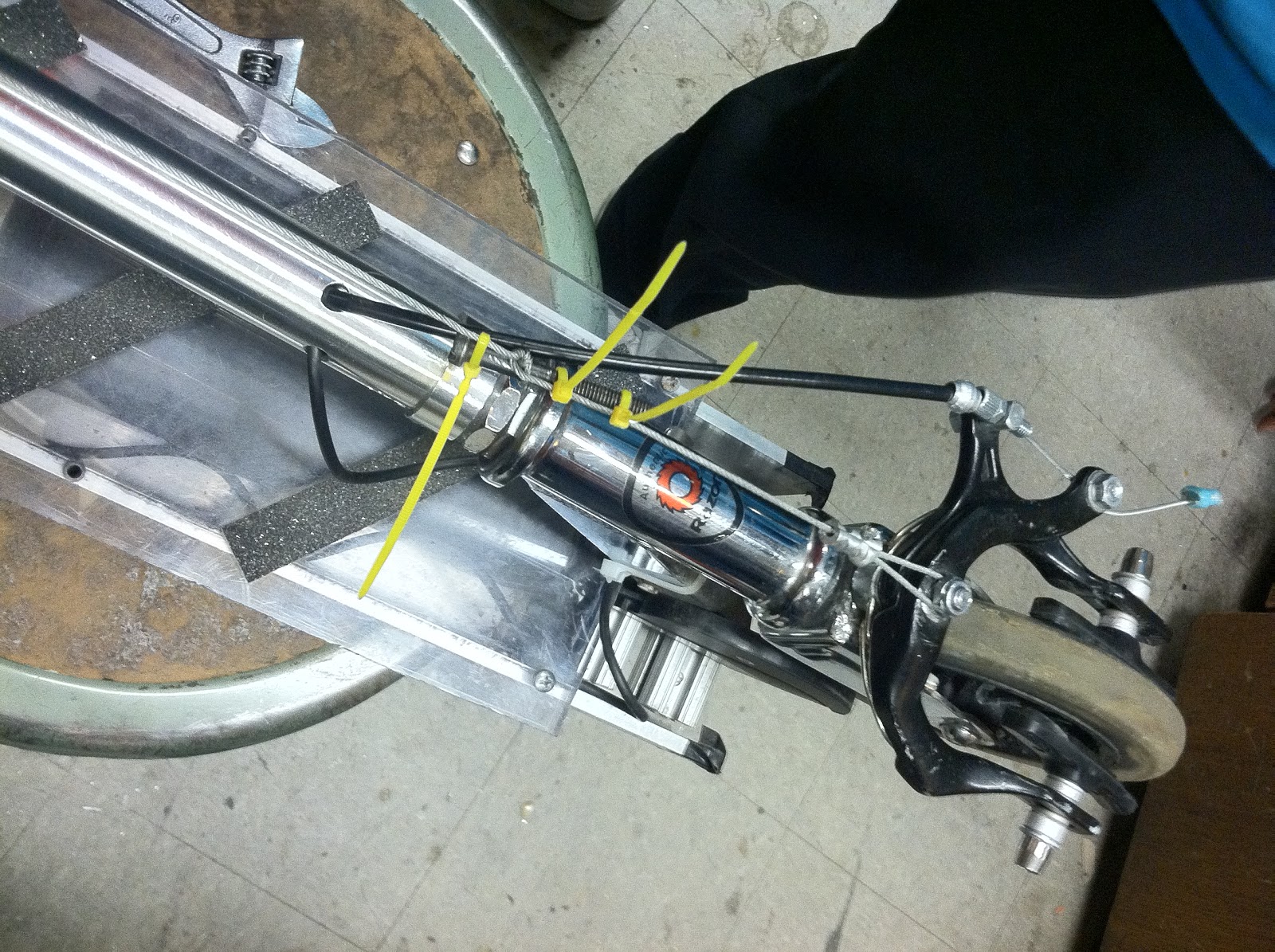
At the advice of Shane, I wrapped the stator to see how many wraps I could reasonably fit onto one tooth.

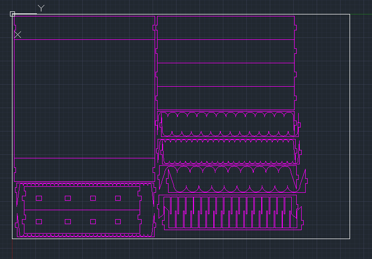
AutoCAD predicts 95 wraps will fit if I wrap really tightly and ensure that each wire fits neatly in the valley of the two under it.


Realistically, I could fit 72 wraps of single strand 22 guage wire around one tooth, leaving room for some airflow and allowing for error in other teeth's wraps.


If we plug in 72 as N in our favorite equation, we get Kt = .248 Nm/A, which is right where it should be. According to Shane, most electric kick scooters have a Kt of between .2 and .3 Nm/A. The higher side of this range will give a scooter more torque, but go slower, and a Kt on the lower side will go faster, but accelerate slower.

Kt = .248 Nm/A


5.55 Nm / .248 Nm/A = 22.4 A


33 v/ .248 v/rad/s) = 133 rad/s

Going the long way again:

130 rad/s * 1 rev/2 pi radians * 60 s/1 min * 60 min/1 hr * 2 pi (3 in)/1 rev * 1 ft/12 in * 1 mile/5280 ft = about 22 mph

This is about right. Fast enough to actually be used as transportation somewhere, and torquey enough to get me up to speed quickly and scare other people who want to try my little toy.

Hopefully I'll wrap the stator sometime in the next two weeks, and then get to the construction of the body, battery, and turning of the rotor can and spacers.

Let the scooter building season begin...

Sunday, November 6, 2011

Scooter Battery Replacement

The original Deathscooter battery was kindly made for the Engineering Design Workshop by Shane Colton. Unfortunately, Shane was pressed for time, so he accidentally wired the battery backwards. We discovered this after we connected the motor controller to the battery and the connection exploded. The wires' colors were 'reversed' via heatshrink tubing, and two new deans connectors were soldered to where the old ones used to be. Oh, and the battery didn't have any balance wires either. This battery should not exist. And so in August I built a new battery pack (same specs: A123 8S2P 4400 mAh 26.4V) to replace the old one. On that fine summer day, I did everything except attach the connectors, which is, you know, kind of important.

2.5 months later, I finally got around to finishing the pack. The reason I hadn't done this sooner is that the battery pack that Shane built hadn't exploded yet, and was still performing well despite my extensive usage sometimes requiring multiple ~70% capacity charges per day. The reason I got around to doing it is the darn thing was sitting in N52 almost fully assembled, and I should really be using the pack with balance wires.

Alright here we go. The first step is to put these little tiny connectors on each of the balance leads and put them in a plastic holder so it can be plugged into the charger. A note for anyone trying to build their own pack: do NOT try to strip, solder, or do anything else to two balance leads at the same time. If you try to cut or strip them both at the same time, they will short together on whichever metal cutting tool you have chosen for the task. You and your pack will not be happy. Strip one wire at a time, solder the connecter, crimp, place in the holder. Repeat as necessary, in that order.

Soldered the deans connector onto the main wires. Pack is operational.

- black white brown backwards rainbow +

And we have our fully operational balanced pack!
Looks like we're done for the day. NOPE.
The pack doesn't fit inside the battery bay on the scooter because the wire sticks out the top instead of the side on part of the pack. The segment of wires in front of the conveniently (and accidentally) placed cinnamon toast crunch box needs to be moved from the top to the side.
Carefully slicing open the pack, I am terrified of cutting a wire or worse, shorting two wires with my knife blade. Luckily neither of those things happened.
Black wire was pushed over to the side, and the pack is ready to be sealed up. Wait...where's my duct tape? Crap. Well, floor mate Julia to the rescue... 

Probably the most colorful pack I will ever make.
It fits!

And so Deathscooter was made a bit more colorful. 

Note: I will still not ride this machine until I get a new front wheel, which is in the mail as of tomorrow (hopefully).

Saturday, October 29, 2011

Wind Tunnel Project

Today I was recruited by Bruno Piazzarolo (MIT 2012) to help design a wind tunnel. I did a quick model in AutoCAD for lasercutting, which we did later that evening. The model I designed is for a very small prototype to be used with a 120mm computer fan that I happened to have in my backpack.The fan is rated to move 30 cubic feet of air per minute and was originally to be used for a fan I had designed, but I guess I'll just order more.

Fancy acrylic spatulas.
We cut two of the above images out of 1/8" acrylic sheet, and then realized something: bending these is going to suck. And so I was commissioned to make a jig to help shape the pieces.


Make x 9

The jig will snap together into two separate pieces that will sandwich the heated acrylic and allow it to bend into the perfect shape for wind-tunnel construction. Update soon to come with the construction of the jig and wind tunnel.

Tuesday, October 25, 2011

Scooter Testing and MORE Brake Repair

Last night from 10-11pm Shane, Charles, Franco, and I did some testing of our scooters in the Albany St. garage. The test consisted of a hill climb from the bottom of the garage to the top level (driving directions: right turn x 20), a distance of about a half mile.

Energy = Power x Time

Deathscooter's results: 11.8 Wh in 78 seconds

11.8 Wh = 544.6W x 78s x 1h/3600s
P=IV
544.6W=26.4V x 20.6A

20.6 Amps average going up the Albany St. garage. Learn something new every day.


"Not enough gang signs."

The Sisters of Anarchy
On to the brake repair portion of the post. Five minutes prior to leaving for the test, I let one of my floor mates who will remain anonymous use my scooter in the hallway. He accidentally made the scooter run itself into a wall which knocked the brakes loose.

"But Adrian, you said the brakes were welded to the front fork!"
"Yeah, J-B Weld."

As a result, the brake calipers now clamped the 'spokes' of the wheel instead of the rim, providing almost no braking at all. On the trip over to MITERS I went full throttle all the way used my shoe to slow down. Good thing I didn't need brakes for the testing.

First attempt: Use picture hanging wire to provide tension to hold the calipers in place.

Looks good, right? No, not right... and not left either.
Now I can't turn.

Attempt 2: Use longer picture hanging wire to provide tension to hold the calipers in place and attach the other end of the wire to something that moves with the wheel.

Several minutes, a screw, and three zip ties later, we have wound the wire around the front of my scooter in such a way that accomplishes our goal. 


Used a screw to tension the wire.

Another discovery during this process: my brake pads are depositing themselves onto the wheel. 

I did reach home safely after this quick fix, but as much as I enjoy the thrill of speculating on whether or not I'll be able to stop the next time I use the brakes, I need to fix this for real. I'm going to try to get access to one of the TIG welders in EMB and mount a steel plate to the front fork, which will hopefully allow for sturdier brake mounting.

Saturday, October 22, 2011

Halloween 2011: Arc Reactor Completed!

Original post here.

First, I'd like to thank Barry and Ben for their help on this project.

After helping out with the WISE program in the morning, I got to work on my arc reactor. I got on the 60 watt epilog around 4, and cutting took about an hour. During this hour, I managed to cut all of the pieces out, and also set fire to some of the kibble from others' projects that had fallen through the grate. I didn't notice this when I was actually cutting the pieces, so the fact that my (what were supposed to be) beautiful acrylic pieces had been toasted certainly put a damper on my day... but not for long! I decided that the pieces needed to be roughed up a bit to get the right amount of light out the front of the reactor, so some sand papered pieces did the trick to distract from the burned parts. I didn't take any pictures because I was too busy hurting my wrist trying to hold on to the thing while sanding it.

I tested each of the 12 3mm LEDs from oznium, and then hot-glued them into their respective slots. Several sticks of hot-glue and ~50 feet of enameled magnet wire later, we have something that resembles a whole bunch of acrylic circles stuck together with some wire wrapped around it.

This is taking way longer than anticipated.

I'm glad I found a use for the wire I took off those printer stators.

On to the electronics. The LEDs were soldered together 4 in parallel, 3 in series. Each string of 3 leds was paired with a 180 Ohm resistor, to give about 35 mA per LED strand.

Not pretty at all, but it's 10:30 and I want to get out of here.

After loose wires were trimmed and glued down to avoid short circuits, the back was glued on, the wires to the battery were added, and I was ready to roll. The final step: embed this in my chest glue this to a cheap shirt and become a genius-billionaire-philanthropist.

Alligator clips not used in final version.
A bit thicker than I would have preferred, but a man's gotta do what a man's gotta do.

If only this thing actually did what it does in the movies.

Friday, October 21, 2011

FIXED: Ibanez SB7 Synth Bass Pedal

Tonight I was presented with two tasks. The first was to repair Garren (roommate a) 's  ripped backpack strap, which I did with gorilla glue and some sloppy needlework. The second task was to fix Pat (roommate b) 's synth bass pedal which had been out of operation for a few months. He claimed that the pedal worked on AC adapter power but not off of the built in battery.

Let'd do this.
And so the quest for 80's grooves began.

The initial disassembly showed some funky internal PCB circuitry which made me doubt that the battery power ever worked. The negative terminal of the 9 volt didn't go anywhere except a long line of solder-covered copper that wrapped around one edge of the main board.

Just...why?

I tested the continuity of the power port and took a moderately educated guess that the negative wire would be the pin in the middle, not the ring surrounding it. Then I desoldered the leads from the battery adapter to the board, and that's when I realized that I didn't have any solder, only a soldering iron. I'm not an EE after all...

Good ol' multimeter.
Please don't be backwards.

And so the battery adapter was "soldered" to where the wall power adapter should go in, and lo and behold, the pedal worked!


A few wire extensions later, the pedal was reassembled and some groovy music was created by our resident bass guitarist, Pat Mars. Yes, that's his real name, yes, he is from our world.


Sunday, October 16, 2011

Halloween 2011

For the first time in 3 (?) years, I will be 'dressing up' for Halloween. I will be Iron Man minus the suit. This leaves the arc reactor and Tony Stark's BAMF quotient. Fortunately, one of those things can be laser cut from acrylic and then glued together and lit up to look pretty.

Hopefully this thing won't weigh too much.

favicon:


Mechanical Iris V2 Update

It works! Well, most of the time. The miniature four-leaved iris that I designed was finally cut at the Saturday Thing. Despite the fact that somebody reserved the 120 watt epilog and didn't show up to use it, we got along just fine with the 60 watt. Also, it's been 8 hours since I was in the FabLab, and I still smell like burnt wood.


If only one could make a living by making random things that serve no purpose.
Notes for next time:

Make it bigger.
One of the reasons that the first iris worked so well is that it's parts were bigger (radius 10") so slight errors in the alignment of the pins affected the overall performance less. With the miniature iris, (radius 4") the best I could do for pins was an assortment of machine screws which leave quite a bit of wiggle room so the parts can misalign themselves and piss me off when I try to use it.

Find better quality wood.
I cut this out of 3/16" luan, which is synonymous with crappy plywood. Every piece of luan that I've come across has been slightly bowed. Laser cutters don't like it when materials are out of the beam's focus, and so in order to inform you of this fact, they leave large scorch marks on the top of your object, and the width of the cut increases greatly.

Make some sort of handle.
As impractical as this thing is, when I do decide to fool around with it, it's tough to hang on to and requires two sizable man-hands to operate smoothly.


Monday, October 10, 2011

Lightswitch Machine

This weekend I visited my parents in good ol' Lexington. I was unpleasantly surprised to find that the system I built to turn my lights on and off had been taken down by parents while I was away.

Before.
We must rebuild.

Friday, October 7, 2011

Deathscooter Brake Replacement Update

Wow. These bike brakes are five times better than the old brakes ever were. I tested them out on Bay State Rd. before I took to the real streets, and I almost flipped over. Oh well... it was either front brakes or no brakes at all. I now have functional (also very sensitive) brakes that will hopefully last until winter, at which point I will probably have to rethink my transportation modes anyway.

Original post here.

Thursday, October 6, 2011

Deathscooter Brake Replacement

Yesterday while riding east down Comm. Ave. I was almost hit by a truck. Twice. The bike lane is never safe. I was wearing a helmet (I think of it as a fashionable plastic hat) which made me feel a little better about the events, but regardless I would have been farther from death if I had full breaking ability, which was currently in short supply. These brakes should have been replaced a few weeks ago, so I can safely say that brake pads have about a month and a half of life on the scooter.


Putting my foot down on the asphalt was more effective than clamping the brakes as hard as I could.

And so I was inspired to travel to a bike shop in kenmore and purchase some $10 bike brake pads. They fit nicely and work very well. I live to ride another day with greater deceleration capabilities.


I'll update on the status of these brakes in a few weeks.

Tuesday, October 4, 2011

Mechanical Iris V2

I should be studying for my calculus exam tomorrow, but instead I designed another mechanical iris. This one has four leaves and was designed from scratch. No help from the internet this time. On my first attempt to design this, I tried to make it have 6 leaves, which I soon discovered is really tricky. It would require more than three layers of parts and a significant chunk of time to design, so I ended up with four leaves.


If this works on the first try, I'll eat my shoe.

Monday, October 3, 2011

Batteries EVERYWHERE

Today the parental units visited me for dinner. They also dropped off about $50 worth of batteries. For the record, I did ask for batteries, I just didn't realize they were to be bought in bulk at Costco. Adding these to my current collection, (along with their incredibly space-inefficient packaging) I found my desk drawer completely filled with Duracell.


Batteries EVERYWHERE

And so the mission began to create a storage system. Using AutoCAD I designed a battery rack that lays flat in the drawer and organizes the portable power sources very nicely.


Magenta is the default color for cutting on the Epilog laser. 

I'll hopefully get around to cutting and assembling this soon.


Saturday, October 1, 2011

Mechanical Iris / More Dome Cutting

Today at the MIT Edgerton Center I cut about 50 more acrylic "dome" pieces for the outreach program. I designed this last summer in AutoCAD and the design is still being used for various programs.

After the 'business' portion of sitting by the lasercutter was done, I cut out a design that I found on thingiverse.com. It's a mechanical iris, that is, it tries to mimic the opening and closing of a natural eye. Unfortunately this design forms a star like shape when it opens because the leaves don't overlap. I aim to design one of my own with more than five (probably 12) thin leaves (material TBD) that will overlap and maintain a roughly circular shape when opening and closing.


Daniel operating the iris:


Update: Fooled around with the pieces a bit, found this alternate configuration:

Sunday, September 18, 2011

Welcome to my blog.

Here I will post updates on projects!

Posts soon to come: 'Deathscooter Maintenance' and '(name TBA) Scooter Construction'

If you would like to hire me, please contact me at atanner@bu.edu

Enjoy,
Adrian