Thursday, September 6, 2012

MRT Alaska Trip - August 2012

After mentoring in the Engineering Design Workshop each day, I worked with the MIT Marine Robotics Team to prepare for a testing trip in Alaska. Over the course of June and July we prepared two gliders for testing in a pool and in open water. One of the gliders was about two and a half feet long and served as a proof-of-concept model and experimental platform for sensors such as GPS, pressure, and dive/rise indicators.

Tommy and Baby glider


The second glider was our main focus. At five feet long and 60 lbs operating weight (about 45 lbs without ballast), it was tons of fun to bring through TSA... twice. After an hour long private security scan and half a day of travel, everything and everyone made it to Ketchikan safely.

Bubble wrap + greenie
The people at Ketchikan Gateway Borough very kindly let us use their dive pool for testing almost every day during the trip. It was an excellent place to test because the pool was nearly empty at 8am and we could easily trim the glider, check for leaks, test sensors, and get great footage from a GoPro mounted on Tom's ROV at the same time.


And they had a slide two slides.


The team also helped with a program called SeaGlide, which introduced middle school students to the world of underwater vehicles and showed them how to make mini-gliders using water bottles and an arduino. The program was spearheaded by Robert Vieth who specializes in STEM outreach in Alaska. Several employees from the Carderock division of NAVSEA also helped with the program.


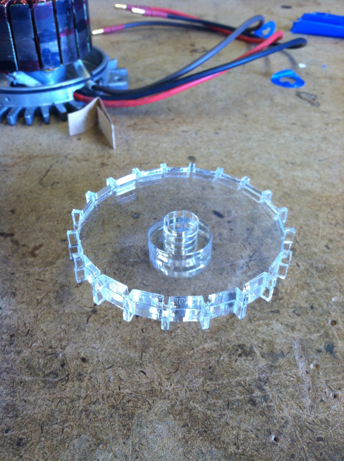
Cleaning up a few of the 3D printed parts with our fancy knives

We also toured SEAFAC, but weren't allowed to take pictures most of the time, probably for a good reason. The best I could do for photos were a few on the boat ride out and one in their machine shop.


Biggest lathe I've ever seen
Lastly, the highlight of the trip happened after we had been given a tour of the mariculture facility and were allowed to test our large glider after showing it to the kids in the SeaGlide program. Gary Freitag was kind enough to let us use his SeaBotix ROV to get footage of the glider in the ocean. It also had a manipulator arm that we could use to grab the glider in case the glider decided it didn't want to come back up. That didn't happen, but the first untethered run was pretty terrifying/awesome anyway.


And so we put the buoyancy engine on a timer, dropped the glider in the ocean, and waited. David was in a kayak and I was piloting the ROV and everyone else was useless. Just kidding, they helped feed the tether off of the 800' spool. 

Warning: the awesomeness of the story that follows is not accurately portrayed over the internet. I'm not even going to try.

- Glider put in water
- Glider floats, refuses to sink despite pleas of MRT
- Two washers zip tied to back of glider
- Glider is pretty darn close to perfectly trimmed
- Glider starts dive cycle
- Dive looks good
- People start to remember that there is no tether
- Excitement ensues
- David is alone outside because everyone is inside looking at the ROV screen
- 20' below surface
- 30' below surface - we reached our target depth for the trip!
- Glider still diving
- People start to freak out
- Tom tells Adrian, "DON'T LOSE THE GLIDER. STAY WITH IT"
- Adrian stays with the glider
- 43' below surface
- GLIDER STARTS TO PULL OUT OF DIVE
- GLIDER COMES BACK UP TO THE SURFACE
- EVERYONE IS GOING CRAZY
- WE DID IT! WE DID IT!
- WOOOOOOOOOO

A video of our most glorious moment, accompanied by appropriate music follows. A few notes: the FS at the bottom stands for Feet Seawater, and the CA stands for Camera Angle. This is how we got our depth reading for the glider.


After we pulled the glider out, we got to have some fun with the ROV. Ed ended up stabbing picking up a sea cucumber from 200' and brought it up. When it got to the surface, it was a bit floppy from the pressure change, but fortunately it didn't evacuate its bowels on us, as sea cucumbers are known to do.

warp speed


"It's what's for dinner"
After returning the sea cucumber to its home and packing up, we merrily feasted on land animals, as seen in the following picture.

Kodak moment


Wednesday, September 5, 2012

Engineering Design Workshop 2012

In July of 2012, The Edgerton Center hosted the annual Engineering Design Workshop. The program brings in high school students from around the world to work in teams on a project of their choice. This year the program had 24 kids and 6 mentors, which turned out to be a pretty good ratio. In addition to the mentors, the workshop had Ed Moriarty and John McGoldrick as general overseers and sources of infinite wisdom.
Ed talking with the kids on the first day
 My group decided to make an autonomous vehicle with the final goal of having it deliver caffeinated beverages to Ed. This goal was never completely achieved, but the wall-avoiding robot we ended up with worked well and everyone involved gained valuable experience.

A few photos along the way:

Yashasvi sitting on David's group's project
People doing things with stuff
Ed skyping in from Alaska for design review and updates
JDOB/UAF/ASRA says hi!
John the shop safety specialist
my first steering assembly
Rolling chassis
Intermediate step: RC vehicle
After staring at the vehicle for a few hours we discovered that unnamed student
had used digital pins when he should have used analog pins
Making the vehicle 'safer'
Battleship group
Single-fan hovercraft group
Batmobile group and the resulting tricycle
Dual-fan hovercraft group
Autonomous vehicle group

And so another Engineering Design Workshop came to a close and some of us went back to a normal sleep schedule and some did not. At the same time as the workshop, three of the six mentors (Jackie, David, and myself) were also preparing to test an underwater glider in Alaska and left for testing the day after the workshop ended. I'll post about that in a few days when I sort through the thousands of photos and videos that were taken on the trip. In the meantime, here's a preview:

$50,000 ROV catches dinner

Monday, June 25, 2012

MiniCycle V2 and DethWhacker

A few weeks ago, MiniCycle V1 was completed and Tom, Shane, Charles, and I went to the garage to do some time trials. This thing is TINY. Due to impatience, we used the old battery from DethScooter, a 26.4V (8S) 4.4 Ah pack I built in September 2011. Also due to impatience, the battery was wedged into a space between the motor controller and the rider's crotch. Not exactly the ideal place to have a battery malfunction. Regardless of battery position and rider vulnerability, the bike had some killer initial acceleration (watch the video) but not a huge top speed, probably about 20 mph.
lol
Tiny and Chibi
Right-side-up videography by Charles Guan.

To fix the problem of the slightly lower than desired top speed, I built another battery pack that would a) go faster and b) fit better into the frame. The pack is 33V nominal (10S) and 4.4Ah. 


Please ignore scorch marks on negative terminal.


Couldn't find heat shrink big enough. Kapton tape and foam to the rescue!


Fits perfectly!


The bike was tested in the Stata Center basement and will hopefully do some garage runs later this summer with the wattmeter and right-side-up video camera.

And now on to the home improvement portion of our show post. Today's task: make the Black and Decker weed whacker a little less... awful. The stock battery was a 18v 1Ah NiCd that supplied about 10 minutes of underwhelming plant mutilation. Sometimes it cut all the way through the plant and didn't just knock it over... Sometimes. Regardless, the first iteration of DethWhacker (named as an homage to DethScooter) uses a 19.8v 2.2Ah battery and is actually kind of terrifying.


Tuesday, May 22, 2012

Summer Project Progress

With my first year at BU finished, I am now free to start as many projects as I think I can complete in the next four months. I have two new projects completely established and started, two tentative ventures having to do with watercraft, and of course that pesky hub motor scooter I've been 'working on' for the past ...10 months or so.

One of the established projects will remain off this blog until a certain friend has a birthday. The other project is a gas-to-electric conversion of a minibike which was kindly donated to me by Charles.

Stripped of all the fancy stuff.
The stator is Delta-wound, which means that if you uncoiled all the teeth and didn't remove any of the electrical connections, you'd have a triangle. My first hub motor is wound in a Wye configuration where all three phases meet in the middle. Delta-wound stators tend to spin faster while producing less torque per amp. If you had two stators of identical dimensions, number of wraps, voltage, etc., but one was wound Delta and the other was wound Wye, the Delta would produce less torque and higher rpm by a factor of √3.

Standard procedure for brushless motors is to open them up to look for stray windings, bad connections, or misaligned magnets. Boy, did I find some misaligned magnets. A quarter of the forty magnets in the can had come off and had clumped together in a few locations. A jig for positioning the magnets was lasercut from .25" acrylic. I wanted it to be clear so I could see both ends of the magnets. The acrylic worked very well, and after the epoxy between the magnets and the can had set for about two hours, I added some epoxy between the magnets to prevent slippage side to side.


N = 51... ?
Magnet meeting
Magnets removed, old epoxy removed, can surface sanded to better accept new epoxy.
Jig for positioning magnets.
Epoxy added to the gaps between magnets to help prevent them from sliding. Looks good! 

After the magnet epoxy was allowed to cure for 24 hours, I brought it to the Edgerton Center shop to try to use a lathe to gently lower the can onto the stator. Credit for this idea goes to Ed Moriarty, and the hands you see in the pictures are those of Mark Belanger, who helped me figure out how to do this and offered to do the procedure due to my damaged left wrist. Mark came up with the idea of turning the end of a shaft to a point that would fit into the tapped hole at the front of the shaft connected to the can. The shaft was held in the chuck on the right, and the can was firmly held in the chuck on the left. The stator assembly was placed over the shaft and was advanced so the two shafts met and could not move. The stator was carefully moved towards the can and was 'sucked' into position while maintaing the proper alignment thanks to the lathe setup. The motor was then fully pushed into its bearings with the tailstock.

Note: lathe was not spinning during these photos. 


It looks the same as it did before, but here's that picture again.