Monday, November 21, 2011

SolidWorks and Engineer Magazine


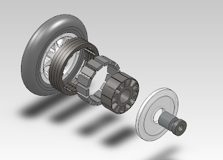
This Saturday, I didn't build anything. Anything physical, that is. Instead I spent several hours learning how to use SolidWorks, which MIT kindly provided for me for free. After several grueling hours of learning the ins and outs of the software and making some lovely extruded polygons, I set out to model my scooter.

Mate. Mate mate. Mate mate mate.
Exploded
This modeling will probably eat up most of my time until I get lazy and just think about the design in my head. That actually isn't such a bad thing, since head-thinking has worked out pretty well so far.

Last but not least, I was interviewed by Mark Dwortzan for Engineer, a semiannual publication about the College of Engineering. The story will be in the spring issue, which will be on the shelves around March (?) of 2012.

Sunday, November 13, 2011

New Scooter

Here's to actually doing projects and having fun doing them. The long anticipated construction of New Scooter (official name TBA, not to be confused with Pneu Scooter) finally got its butt off the couch and went to the whiteboard for some calculations.

So lets say that I want to be able to climb a 10% grade on my scooter.

F = mg sin(theta)
F = 75 kg * 9.8 m/s^2 * .1
F = 73 N

This means that the force of gravity pulling me back down the hill is 73 N, and that I want 73 N pushing me up the hill. Lets say I want to climb the hill at 5 m/s.

P = linear force * linear velocity
P = 73 N * 5 m/s
P = 365 W

Torque = Force * radius, and I have a 6" diameter wheel.


T = F * r
T = 73 N * .076 m
T = 5.55 Nm

I'm planning on building a 33 volt LiFePO4 battery.


365 W = 33 v * 11.1 A

Now for my new favorite equation: Tea is for nibbler. I mean T = 4NIBLR

That is, Torque = 4 * # of wraps * Current * Strength of magnetic field * Length of stator * Radius of stator

For this calculation, we will estimate that the B field is about 1 T. This is an estimation, but it's really not far off of the actual value.

T = 4NIBLR
N = T/4IBLR
N = 5.55 Nm / 4 * 11.1 A * 1 T * .0254 m * .034 m
N = 144 wraps per phase

Now lets say the maximum current through quadruple 22 guage (four strands in parallel) wire is 40 amps peak. Replacing the 11.1 A in the equation with 40 A, we get N = 40 turns per phase.

If A = 11.1, N = 144 to get me up the hill.
If A = 40, N = 40 to get me up the hill.

Now for the torque constant, in Nm/A.

Kt = T/I = 4NBLR


For 11.1 A we get .5 Nm/A
For 40 A we get .14 Nm/A

1 Nm/A = 1 V/(radian/s)


33 v/(.5 v/rad/s) = 66 rad/s
and
33 v/ (.14 v/rad/s) = 236 rad/s

To calculate speed

66 rad/s * 1 rev/2 pi radians * 60 s/1 min * 60 min/1 hr * 2 pi (3 in)/1 rev * 1 ft/12 in * 1 mile/5280 ft = 11.2 mph

This is too slow. Well actually, it's a pretty safe speed, and at about twice the speed of me comfortably jogging somewhere, I'd be pretty happy going that speed. However, I'd like to go a little faster, so let's calculate my speed if I used the 40 A + N = 40 configuration. By multiplying by 236/66 we get 40 mph. As crazy as I am, I'd like to be able to build more vehicles after this project, so let's see if we can get something a bit slower.

At the advice of Shane, I wrapped the stator to see how many wraps I could reasonably fit onto one tooth.

AutoCAD predicts 95 wraps will fit if I wrap really tightly and ensure that each wire fits neatly in the valley of the two under it.


Realistically, I could fit 72 wraps of single strand 22 guage wire around one tooth, leaving room for some airflow and allowing for error in other teeth's wraps.


If we plug in 72 as N in our favorite equation, we get Kt = .248 Nm/A, which is right where it should be. According to Shane, most electric kick scooters have a Kt of between .2 and .3 Nm/A. The higher side of this range will give a scooter more torque, but go slower, and a Kt on the lower side will go faster, but accelerate slower.

Kt = .248 Nm/A


5.55 Nm / .248 Nm/A = 22.4 A


33 v/ .248 v/rad/s) = 133 rad/s

Going the long way again:

130 rad/s * 1 rev/2 pi radians * 60 s/1 min * 60 min/1 hr * 2 pi (3 in)/1 rev * 1 ft/12 in * 1 mile/5280 ft = about 22 mph

This is about right. Fast enough to actually be used as transportation somewhere, and torquey enough to get me up to speed quickly and scare other people who want to try my little toy.

Hopefully I'll wrap the stator sometime in the next two weeks, and then get to the construction of the body, battery, and turning of the rotor can and spacers.

Let the scooter building season begin...

Sunday, November 6, 2011

Scooter Battery Replacement

The original Deathscooter battery was kindly made for the Engineering Design Workshop by Shane Colton. Unfortunately, Shane was pressed for time, so he accidentally wired the battery backwards. We discovered this after we connected the motor controller to the battery and the connection exploded. The wires' colors were 'reversed' via heatshrink tubing, and two new deans connectors were soldered to where the old ones used to be. Oh, and the battery didn't have any balance wires either. This battery should not exist. And so in August I built a new battery pack (same specs: A123 8S2P 4400 mAh 26.4V) to replace the old one. On that fine summer day, I did everything except attach the connectors, which is, you know, kind of important.

2.5 months later, I finally got around to finishing the pack. The reason I hadn't done this sooner is that the battery pack that Shane built hadn't exploded yet, and was still performing well despite my extensive usage sometimes requiring multiple ~70% capacity charges per day. The reason I got around to doing it is the darn thing was sitting in N52 almost fully assembled, and I should really be using the pack with balance wires.

Alright here we go. The first step is to put these little tiny connectors on each of the balance leads and put them in a plastic holder so it can be plugged into the charger. A note for anyone trying to build their own pack: do NOT try to strip, solder, or do anything else to two balance leads at the same time. If you try to cut or strip them both at the same time, they will short together on whichever metal cutting tool you have chosen for the task. You and your pack will not be happy. Strip one wire at a time, solder the connecter, crimp, place in the holder. Repeat as necessary, in that order.

Soldered the deans connector onto the main wires. Pack is operational.

- black white brown backwards rainbow +

And we have our fully operational balanced pack!
Looks like we're done for the day. NOPE.
The pack doesn't fit inside the battery bay on the scooter because the wire sticks out the top instead of the side on part of the pack. The segment of wires in front of the conveniently (and accidentally) placed cinnamon toast crunch box needs to be moved from the top to the side.
Carefully slicing open the pack, I am terrified of cutting a wire or worse, shorting two wires with my knife blade. Luckily neither of those things happened.
Black wire was pushed over to the side, and the pack is ready to be sealed up. Wait...where's my duct tape? Crap. Well, floor mate Julia to the rescue... 

Probably the most colorful pack I will ever make.
It fits!

And so Deathscooter was made a bit more colorful. 

Note: I will still not ride this machine until I get a new front wheel, which is in the mail as of tomorrow (hopefully).