With my first year at BU finished, I am now free to start as many projects as I think I can complete in the next four months. I have two new projects completely established and started, two tentative ventures having to do with watercraft, and of course that pesky hub motor scooter I've been 'working on' for the past ...10 months or so.
One of the established projects will remain off this blog until a certain friend has a birthday. The other project is a gas-to-electric conversion of a minibike which was kindly donated to me by
Charles.
 |
| Stripped of all the fancy stuff. |
The stator is Delta-wound, which means that if you uncoiled all the teeth and didn't remove any of the electrical connections, you'd have a triangle. My first hub motor is wound in a Wye configuration where all three phases meet in the middle. Delta-wound stators tend to spin faster while producing less torque per amp. If you had two stators of identical dimensions, number of wraps, voltage, etc., but one was wound Delta and the other was wound Wye, the Delta would produce less torque and higher rpm by a factor of √3.
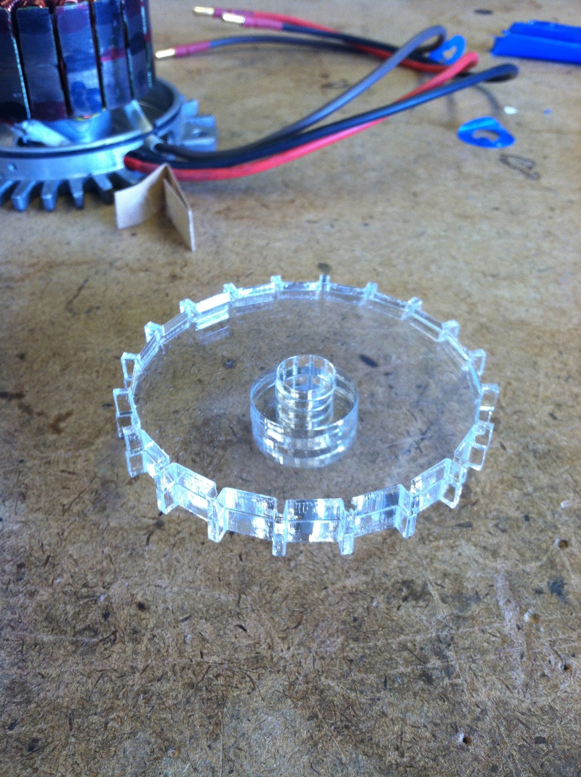
Standard procedure for brushless motors is to open them up to look for stray windings, bad connections, or misaligned magnets. Boy, did I find some misaligned magnets. A quarter of the forty magnets in the can had come off and had clumped together in a few locations. A jig for positioning the magnets was lasercut from .25" acrylic. I wanted it to be clear so I could see both ends of the magnets. The acrylic worked very well, and after the epoxy between the magnets and the can had set for about two hours, I added some epoxy between the magnets to prevent slippage side to side.
 |
| N = 51... ? |
 |
| Magnet meeting |
 |
| Magnets removed, old epoxy removed, can surface sanded to better accept new epoxy. |
 |
| Jig for positioning magnets. |
 |
| Epoxy added to the gaps between magnets to help prevent them from sliding. Looks good! |
After the magnet epoxy was allowed to cure for 24 hours, I brought it to the Edgerton Center shop to try to use a lathe to gently lower the can onto the stator. Credit for this idea goes to Ed Moriarty, and the hands you see in the pictures are those of Mark Belanger, who helped me figure out how to do this and offered to do the procedure due to my damaged left wrist. Mark came up with the idea of turning the end of a shaft to a point that would fit into the tapped hole at the front of the shaft connected to the can. The shaft was held in the chuck on the right, and the can was firmly held in the chuck on the left. The stator assembly was placed over the shaft and was advanced so the two shafts met and could not move. The stator was carefully moved towards the can and was 'sucked' into position while maintaing the proper alignment thanks to the lathe setup. The motor was then fully pushed into its bearings with the tailstock.
 |
| Note: lathe was not spinning during these photos. |
 |
| It looks the same as it did before, but here's that picture again. |


I think your equations broke. Also wasn't that bike always electric?
ReplyDeleteFormatting fixed, and that's true so I guess I'm 're-electrifying' it!
DeleteThis comment has been removed by the author.
ReplyDeletewhere did you get that motor? it looks interesting in quality and build but also looks good for experimenting with ev's and custom motor controllers.
ReplyDeleteMark, here's a link to the motor's manufacturer's website. It's original purpose was for an e-bike.
ReplyDeletehttp://www.evdeals.com/Motors.htm#BMC-MAC%20600W%20%28bike,%20USPD,%20Pro-Drive%29
It's the MAC 600W, however the stock motor is sold with ferrite magnets. It now has neodymium magnets so it can be run at a higher voltage and put out more power.